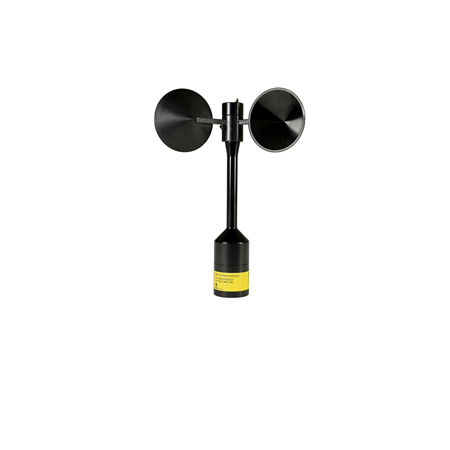
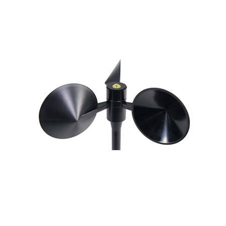
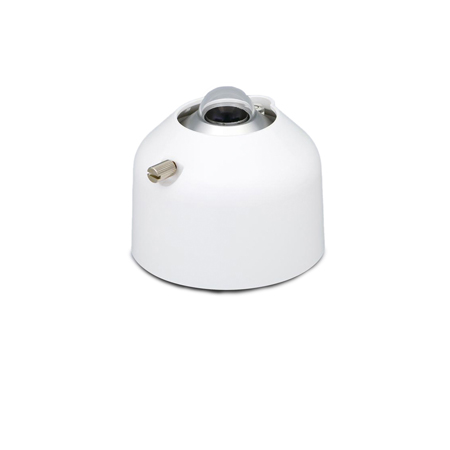
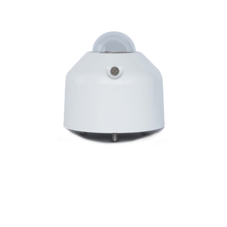
The NRG S1 Anemometer provides a unique balance of high accuracy and low cost, making it ideal for reducing measurement uncertainty in wind resource assessment campaigns as well as power performance tests. A proven bearing system and a rugged, metal body design ensure the sensor will operate reliably for many years, in a variety of environmental conditions.
CLASSIFICATION
The NRG S1 Anemometer is the only wind energy anemometer classified to both editions of the IEC 61400-12-1 standard, enabling straightforward comparisons against both new and legacy anemometers.
| IEC 61400-12-1 | Edition 1 (2005) | Edition 2 (2017) |
|
Class A |
1.21 |
1.27 |
|
Class B |
3.86 |
4.19 |
|
Class C |
N/A |
4.15 |
|
Class D |
N/A |
6.13 |
MEASNET Calibrated (#9405) |
MEASNET Calibrated, SOH CPH (#9415) | MEASNET Calibrated, DWG (#9416) | MEASNET Calibrated (2) (#14363) | MEASNET Calibrated, SOH CPH (2) (#14364) | MEASNET Calibrated, DWG (2) (#14365) | |
|---|---|---|---|---|---|---|
DESCRIPTION |
||||||
| Sensor type | 3-Cup Anemometer | 3-Cup Anemometer | 3-Cup Anemometer | 3-Cup Anemometer | 3-Cup Anemometer | 3-Cup Anemometer |
| Applications |
|
|
|
|
|
|
| Sensor range | 0.638 m/s to 75 m/s (1.427 mph to 167.8 mph) | 0.638 m/s to 75 m/s (1.427 mph to 167.8 mph) | 0.638 m/s to 75 m/s (1.427 mph to 167.8 mph) | 0.638 m/s to 75 m/s (1.427 mph to 167.8 mph) | 0.638 m/s to 75 m/s (1.427 mph to 167.8 mph) | 0.638 m/s to 75 m/s (1.427 mph to 167.8 mph) |
| Instrument compatibility | All NRG Systems Data Loggers | All NRG Systems Data Loggers | All NRG Systems Data Loggers | All NRG Systems Data Loggers | All NRG Systems Data Loggers | All NRG Systems Data Loggers |
| Measurement range | 0.6 to 75 m/s | 0.6 to 75 m/s | 0.6 to 75 m/s | 0.6 to 75 m/s | 0.6 to 75 m/s | 0.6 to 75 m/s |
OUTPUT SIGNAL |
||||||
| Signal type | Form: Square Wave Frequency: 532.9 Hz @ 50 m/s (112 mph) Amplitude: Equal to supply voltage, max. 15 V |
Form: Square Wave Frequency: 532.9 Hz @ 50 m/s (112 mph) Amplitude: Equal to supply voltage, max. 15 V |
Form: Square Wave Frequency: 532.9 Hz @ 50 m/s (112 mph) Amplitude: Equal to supply voltage, max. 15 V |
Form: Square Wave Frequency: 532.9 Hz @ 50 m/s (112 mph) Amplitude: Equal to supply voltage, max. 15 V |
Form: Square Wave Frequency: 532.9 Hz @ 50 m/s (112 mph) Amplitude: Equal to supply voltage, max. 15 V |
Form: Square Wave Frequency: 532.9 Hz @ 50 m/s (112 mph) Amplitude: Equal to supply voltage, max. 15 V |
| Linearity | Refer to R^2 value on individual calibration report. | Refer to R^2 value on individual calibration report. | Refer to R^2 value on individual calibration report. | Refer to R^2 value on individual calibration report. | Refer to R^2 value on individual calibration report. | Refer to R^2 value on individual calibration report. |
| Anemometer Transfer Function |
|
|
|
|
|
|
| Calibration | Each anemometer individually calibrated at SOH WE, Williston, VT USA. Calibration reports provided via electronic download. |
Each anemometer individually calibrated at SOH CPH, Copenhagen, DK. Calibration reports provided via electronic download. |
Each anemometer individually calibrated at DWG, Varel, DE. Calibration reports provided via electronic download. |
Each anemometer individually calibrated at SOH WE, Williston, VT USA. Calibration reports provided via electronic download. |
Each anemometer individually calibrated at SOH CPH, Copenhagen, DK. Calibration reports provided via electronic download. |
Each anemometer individually calibrated at DWG, Varel, DE. Calibration reports provided via electronic download. |
| Output signal range | 0 Hz to 800 Hz | 0 Hz to 800 Hz | 0 Hz to 800 Hz | 0 Hz to 800 Hz | 0 Hz to 800 Hz | 0 Hz to 800 Hz |
| Resolution | 0.046 m/s | 0.046 m/s | 0.046 m/s | 0.046 m/s | 0.046 m/s | 0.046 m/s |
| Uncertainty | IEC 61400-12-1 Ed. 1 Classification
|
IEC 61400-12-1 Ed. 1 Classification
|
IEC 61400-12-1 Ed. 1 Classification
|
IEC 61400-12-1 Ed. 1 Classification
|
IEC 61400-12-1 Ed. 1 Classification
|
IEC 61400-12-1 Ed. 1 Classification
|
RESPONSE CHARACTERISTICS |
||||||
| Threshold | 0.638 m/s (1.427 mph) per ASTM D 5096-02 | 0.638 m/s (1.427 mph) per ASTM D 5096-02 | 0.638 m/s (1.427 mph) per ASTM D 5096-02 | 0.638 m/s (1.427 mph) per ASTM D 5096-02 | 0.638 m/s (1.427 mph) per ASTM D 5096-02 | 0.638 m/s (1.427 mph) per ASTM D 5096-02 |
| Distance constant (63% recovery) | 2.76 m (9.05 ft) per ASTM D 5096-02 | 2.76 m (9.05 ft) per ASTM D 5096-02 | 2.76 m (9.05 ft) per ASTM D 5096-02 | 2.76 m (9.05 ft) per ASTM D 5096-02 | 2.76 m (9.05 ft) per ASTM D 5096-02 | 2.76 m (9.05 ft) per ASTM D 5096-02 |
| Moment of inertia |
|
|
|
|
|
|
POWER REQUIREMENTS |
||||||
| Supply voltage | 5 to 28 VDC | 5 to 28 VDC | 5 to 28 VDC | 5 to 28 VDC | 5 to 28 VDC | 5 to 28 VDC |
| Supply current | 0.9 mA at 12V | 0.9 mA at 12V | 0.9 mA at 12V | 0.9 mA at 12V | 0.9 mA at 12V | 0.9 mA at 12V |
INSTALLATION |
||||||
| Mounting | Onto a 25 mm (1") diameter mast with 2 set screws | Onto a 25 mm (1") diameter mast with 2 set screws | Onto a 25 mm (1") diameter mast with 2 set screws | Onto a 25 mm (1") diameter mast with 2 set screws | Onto a 25 mm (1") diameter mast with 2 set screws | Onto a 25 mm (1") diameter mast with 2 set screws |
| Tools required | 2.5 mm Allen Key | 2.5 mm Allen Key | 2.5 mm Allen Key | 2.5 mm Allen Key | 2.5 mm Allen Key | 2.5 mm Allen Key |
ENVIRONMENTAL |
||||||
| Operating temperature range | -30 °C to 60 °C (-22 °F to 140 °F) | -30 °C to 60 °C (-22 °F to 140 °F) | -30 °C to 60 °C (-22 °F to 140 °F) | -30 °C to 60 °C (-22 °F to 140 °F) | -30 °C to 60 °C (-22 °F to 140 °F) | -30 °C to 60 °C (-22 °F to 140 °F) |
| Operating humidity range | 0 to 100% RH | 0 to 100% RH | 0 to 100% RH | 0 to 100% RH | 0 to 100% RH | 0 to 100% RH |
| Lifespan | > 2 years at most sites | > 2 years at most sites | > 2 years at most sites | > 2 years at most sites | > 2 years at most sites | > 2 years at most sites |
| Other |
|
|
|
|
|
|
PHYSICAL |
||||||
| Connections | M12 Connector | M12 Connector | M12 Connector | M12 Connector | M12 Connector | M12 Connector |
| Cable length | Various available | Various available | Various available | Various available | Various available | Various available |
| Weight | Sensor weight = 190 grams (0.42 lbs) | Sensor weight = 190 grams (0.42 lbs) | Sensor weight = 190 grams (0.42 lbs) | Sensor weight = 190 grams (0.42 lbs) | Sensor weight = 190 grams (0.42 lbs) | Sensor weight = 190 grams (0.42 lbs) |
| Dimensions |
|
|
|
|
|
|
MATERIALS |
||||||
| Cups | One piece injection-molded black polycarbonate | One piece injection-molded black polycarbonate | One piece injection-molded black polycarbonate | One piece injection-molded black polycarbonate | One piece injection-molded black polycarbonate | One piece injection-molded black polycarbonate |
| Body | Anodized Aluminium | Anodized Aluminium | Anodized Aluminium | Anodized Aluminium | Anodized Aluminium | Anodized Aluminium |
| Shaft | Stainless Steel | Stainless Steel | Stainless Steel | Stainless Steel | Stainless Steel | Stainless Steel |
| Bearing | Ball Bearings | Ball Bearings | Ball Bearings | Ball Bearings | Ball Bearings | Ball Bearings |
| Signal generator | Optical Switch | Optical Switch | Optical Switch | Optical Switch | Optical Switch | Optical Switch |
Related Products

SRM System
Whether tracking or fixed, mono- or bifacial, 3 MW or 300 MW, NRG is focused on delivering repeatable solar resource measurements across your fleet of projects.

SRA System
NRG Systems’ SRA System is a complete and integrated measurement solution for the prospecting and formal resource assessment of utility-scale photovoltaic projects.
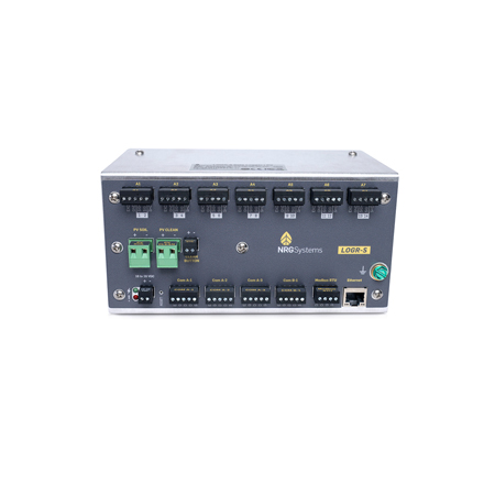
LOGR-S data logger
LOGR-S is NRG Systems’ first data logger designed specifically for the solar energy industry.

NRG PVT1 PV temperature sensor
Because temperature has a significant impact on the performance of operational PV solar systems, PV module temperature is one of the most critical measurements to monitor and analyze.

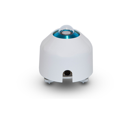
Li-Cor LI-200R pyranometer
The LI-200R measures Global Horizontal Irradiance (GHI) – the combination of Direct Normal Irradiance (DNI) and Diffuse horizontal irradiance (DHI).
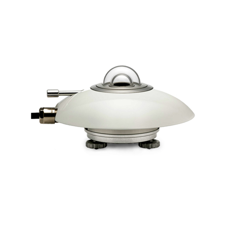
Hukseflux SR20 pyranometer
Recommended when measurement accuracy is the top priority, the Hukseflux SR20 is a thermopile pyranometer that is compliant with the highest category in the ISO 9060 standard: class A (Secondary Standard).
EKO MS-40 pyranometer
The MS-40 Pyranometer is an ISO 9060-2018 Class C pyranometer that measures solar irradiance across the full Solar spectrum at a reasonable cost.
EKO MS-60 pyranometer
The MS-60 Pyranometer is an ISO 9060-2018 Class B pyranometer with a millivolt analog output. The sensor features a double dome construction for lower offsets and cosine errors.
EKO MS-80 pyranometer
The MS-80 Pyranometer is a unique pyranometer compliant to the “Fast response” and “Spectrally flat” sub-categories under ISO 9060:2018 Class A.
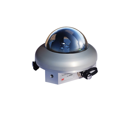
Delta-T SPN1 sunshine pyranometer
The Delta-T SPN1 Sunshine Pyranometer measures global (total) and diffuse horizontal irradiance as well as sunshine duration.

Hukseflux SR30-D1 pyranometer
The SR30 from Hukseflux provides class A (secondary standard) performance per ISO 9060:2018 along with a rich set of features that are unmatched by other sensors.

EKO ms-80S pyranometer
The MS-80S Pyranometer is a unique pyranometer compliant to the “Fast response” and “Spectrally flat” sub-categories under ISO 9060:2018 Class A.

