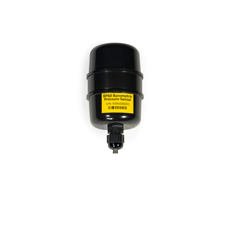
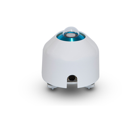
BP60 Barometric pressure sensor – solar
The NRG BP60 Barometric Pressure Sensor is well-suited for the barometric pressure measurement requirements of wind and solar energy studies, particularly as an input to air density, annual energy production calculations, and more reliable forecasts on operational solar and wind farms.
The BP60 introduces a new sensing element, dramatically improving the accuracy of barometric pressure measurements compared to the legacy BP20 sensor. The most significant enhancement is the introduction of native temperature-compensation, discussed in greater detail on the NRG blog.
Each BP60 unit undergoes a single-point check to confirm performance within the sensor’s specifications, the results of which are available in a factory verification certificate at no additional cost. A three-point calibration is also available.
*Please note: BP60C is the calibrated version of this sensor.
1.5m cable - Calibrated (#14611) |
1.5m cable (#14610) | 67m cable (#14612) | 90m cable (#14613) | 110m cable (#14614) | |
|---|---|---|---|---|---|
DESCRIPTION |
|||||
| Sensor type | Analog barometric pressure sensor based on piezo resistive silicon membrane | Analog barometric pressure sensor based on piezo resistive silicon membrane | Analog barometric pressure sensor based on piezo resistive silicon membrane | Analog barometric pressure sensor based on piezo resistive silicon membrane | Analog barometric pressure sensor based on piezo resistive silicon membrane |
| Applications |
|
|
|
|
|
| Sensor range | 500 hPa to 1100 hPa (14.765 to 32.483 inches Hg) | 500 hPa to 1100 hPa (14.765 to 32.483 inches Hg) | 500 hPa to 1100 hPa (14.765 to 32.483 inches Hg) | 500 hPa to 1100 hPa (14.765 to 32.483 inches Hg) | 500 hPa to 1100 hPa (14.765 to 32.483 inches Hg) |
| Instrument compatibility | All NRG Data Loggers | All NRG Data Loggers | All NRG Data Loggers | All NRG Data Loggers | All NRG Data Loggers |
| Signal conditioning module |
|
|
|
|
|
OUTPUT SIGNAL |
|||||
| Signal type | Linear analog voltage | Linear analog voltage | Linear analog voltage | Linear analog voltage | Linear analog voltage |
| Transfer function | Absolute Pressure in hPa = (Voltage x 244.192829) + 494.948781 typical Absolute Pressure in inches Hg = (Voltage x 7.211029) + 14.615867 typical Note: Transfer function above applies to 1.5-meter cable. For sensors with cable lengths longer than 1.5 meters, subtract 0.015949406 hPa (0.00047098563 inHg) per additional meter. |
Absolute Pressure in hPa = (Voltage x 244.192829) + 494.948781 typical Absolute Pressure in inches Hg = (Voltage x 7.211029) + 14.615867 typical Note: Transfer function above applies to 1.5-meter cable. For sensors with cable lengths longer than 1.5 meters, subtract 0.015949406 hPa (0.00047098563 inHg) per additional meter. |
Absolute Pressure in hPa = (Voltage x 244.192829) + 494.948781 typical Absolute Pressure in inches Hg = (Voltage x 7.211029) + 14.615867 typical Note: Transfer function above applies to 1.5-meter cable. For sensors with cable lengths longer than 1.5 meters, subtract 0.015949406 hPa (0.00047098563 inHg) per additional meter. |
Absolute Pressure in hPa = (Voltage x 244.192829) + 494.948781 typical Absolute Pressure in inches Hg = (Voltage x 7.211029) + 14.615867 typical Note: Transfer function above applies to 1.5-meter cable. For sensors with cable lengths longer than 1.5 meters, subtract 0.015949406 hPa (0.00047098563 inHg) per additional meter. |
Absolute Pressure in hPa = (Voltage x 244.192829) + 494.948781 typical Absolute Pressure in inches Hg = (Voltage x 7.211029) + 14.615867 typical Note: Transfer function above applies to 1.5-meter cable. For sensors with cable lengths longer than 1.5 meters, subtract 0.015949406 hPa (0.00047098563 inHg) per additional meter. |
| Accuracy | Uncertainty (k = 2):
|
Uncertainty (k = 2):
|
Uncertainty (k = 2):
|
Uncertainty (k = 2):
|
Uncertainty (k = 2):
|
| Electrical time constant | 1 second | 1 second | 1 second | 1 second | 1 second |
| Calibration |
|
|
|
|
|
| Output signal range | 0.020 to 2.480 VDC | 0.020 to 2.480 VDC | 0.020 to 2.480 VDC | 0.020 to 2.480 VDC | 0.020 to 2.480 VDC |
| Turn on time | < 20 ms | < 20 ms | < 20 ms | < 20 ms | < 20 ms |
| Resolution | 0.0092 hPa (0.0027 inHg) | 0.0092 hPa (0.0027 inHg) | 0.0092 hPa (0.0027 inHg) | 0.0092 hPa (0.0027 inHg) | 0.0092 hPa (0.0027 inHg) |
| Drift | ± 1.0 hPa per year | ± 1.0 hPa per year | ± 1.0 hPa per year | ± 1.0 hPa per year | ± 1.0 hPa per year |
POWER REQUIREMENTS |
|||||
| Supply voltage |
|
|
|
|
|
| Supply current |
|
|
|
|
|
INSTALLATION |
|||||
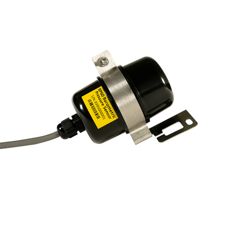
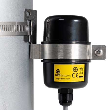
| Mounting |
|
|
|
|
|
| Tools required | 8 mm (5/16 inch) nut driver or flat blade screwdriver | 8 mm (5/16 inch) nut driver or flat blade screwdriver | 8 mm (5/16 inch) nut driver or flat blade screwdriver | 8 mm (5/16 inch) nut driver or flat blade screwdriver | 8 mm (5/16 inch) nut driver or flat blade screwdriver |
| Accessories | BP60 Mounting Bracket available for secure up-tower installations. | BP60 Mounting Bracket available for secure up-tower installations. | BP60 Mounting Bracket available for secure up-tower installations. | BP60 Mounting Bracket available for secure up-tower installations. | BP60 Mounting Bracket available for secure up-tower installations. |
| Wiring | Wire leads:
|
Wire leads:
|
Wire leads:
|
Wire leads:
|
Wire leads:
|
ENVIRONMENTAL |
|||||
| Operating temperature range | -40 to 70°C (-40 to 158°F) | -40 to 70°C (-40 to 158°F) | -40 to 70°C (-40 to 158°F) | -40 to 70°C (-40 to 158°F) | -40 to 70°C (-40 to 158°F) |
| Operating humidity range | 0 to 100% RH | 0 to 100% RH | 0 to 100% RH | 0 to 100% RH | 0 to 100% RH |
| Lifespan | 2 years + | 2 years + | 2 years + | 2 years + | 2 years + |
| Other |
|
|
|
|
|
PHYSICAL |
|||||
| Cable length | 1.5m (5 ft) | 1.5m (5 ft) | 67m (220 ft) | 90m (295 ft) | 110m (361 ft) |
| Weight | 0.12 kg (0.27 lbs) | 0.12 kg (0.27 lbs) | 2.55 kg (5.63 lbs) | 3.41 kg (7.51 lbs) | 4.15 kg (9.14 lbs) |
| Dimensions | 55 mm (2.15") diameter x 101 mm (4.0") tall including cable gland | 55 mm (2.15") diameter x 101 mm (4.0") tall including cable gland | 55 mm (2.15") diameter x 101 mm (4.0") tall including cable gland | 55 mm (2.15") diameter x 101 mm (4.0") tall including cable gland | 55 mm (2.15") diameter x 101 mm (4.0") tall including cable gland |
MATERIALS |
|||||
| Cable | 3 conductor 22 AWG, with overall foil shield and drain wire, PVC jacket | 3 conductor 22 AWG, with overall foil shield and drain wire, PVC jacket | 3 conductor 22 AWG, with overall foil shield and drain wire, PVC jacket | 3 conductor 22 AWG, with overall foil shield and drain wire, PVC jacket | 3 conductor 22 AWG, with overall foil shield and drain wire, PVC jacket |
| Enclosure | Weatherproof black ASA | Weatherproof black ASA | Weatherproof black ASA | Weatherproof black ASA | Weatherproof black ASA |
- Improved sensor accuracy thanks to a new sensing element means lower measurement uncertainty
- Native temperature-compensation enables more reliable forecasts on operational solar and wind farms
Related Products

SRM System
Whether tracking or fixed, mono- or bifacial, 3 MW or 300 MW, NRG is focused on delivering repeatable solar resource measurements across your fleet of projects.

SRA System
NRG Systems’ SRA System is a complete and integrated measurement solution for the prospecting and formal resource assessment of utility-scale photovoltaic projects.
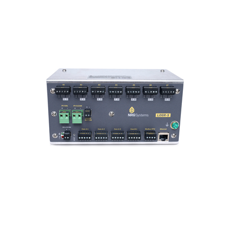
LOGR-S data logger
LOGR-S is NRG Systems’ first data logger designed specifically for the solar energy industry.

NRG PVT1 PV temperature sensor
Because temperature has a significant impact on the performance of operational PV solar systems, PV module temperature is one of the most critical measurements to monitor and analyze.

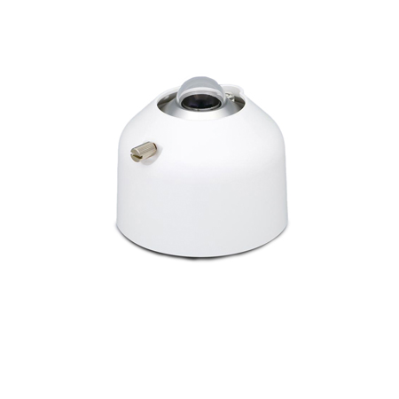
Li-Cor LI-200R pyranometer
The LI-200R measures Global Horizontal Irradiance (GHI) – the combination of Direct Normal Irradiance (DNI) and Diffuse horizontal irradiance (DHI).
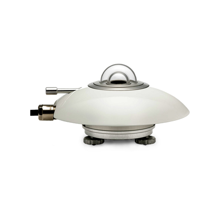
Hukseflux SR20 pyranometer
Recommended when measurement accuracy is the top priority, the Hukseflux SR20 is a thermopile pyranometer that is compliant with the highest category in the ISO 9060 standard: class A (Secondary Standard).
EKO MS-40 pyranometer
The MS-40 Pyranometer is an ISO 9060-2018 Class C pyranometer that measures solar irradiance across the full Solar spectrum at a reasonable cost.
EKO MS-60 pyranometer
The MS-60 Pyranometer is an ISO 9060-2018 Class B pyranometer with a millivolt analog output. The sensor features a double dome construction for lower offsets and cosine errors.
EKO MS-80 pyranometer
The MS-80 Pyranometer is a unique pyranometer compliant to the “Fast response” and “Spectrally flat” sub-categories under ISO 9060:2018 Class A.
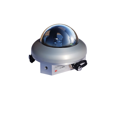
Delta-T SPN1 sunshine pyranometer
The Delta-T SPN1 Sunshine Pyranometer measures global (total) and diffuse horizontal irradiance as well as sunshine duration.

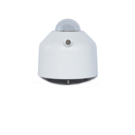
Hukseflux SR30-D1 pyranometer
The SR30 from Hukseflux provides class A (secondary standard) performance per ISO 9060:2018 along with a rich set of features that are unmatched by other sensors.

EKO ms-80S pyranometer
The MS-80S Pyranometer is a unique pyranometer compliant to the “Fast response” and “Spectrally flat” sub-categories under ISO 9060:2018 Class A.

